How to Choose a 1 Axis Solar Tracking System?

Time:2026-10-17 Author:Mason
0%

Choosing a 1 Axis Tracking Solar Panel system begins with the site, not the brochure. Land slope, row spacing, wind exposure, soil conditions, and grid requirements all affect the final result. A tracker may capture more morning and afternoon sunlight, but its value depends on local weather and project design.

Dan Shugar, founder of NEXTracker, has said, “Trackers are a proven, bankable technology for maximizing solar energy production.” This view reflects years of commercial deployment, yet it should not end the evaluation. Bankable does not mean suitable everywhere. A steep site, weak soil, or limited maintenance access can reduce expected returns.

Look closely.

This guide examines the practical decisions behind a 1 Axis Tracking Solar Panel installation. It considers energy yield, mechanical reliability, control systems, installation labor, and long-term maintenance. For example, a tracker moving across a dry field may face dust around drive components. In a coastal project, salt air can create a different maintenance burden. These details are easy to overlook.

The highest output estimate is not always the best choice. A lower-cost system may require more inspections. A premium system may need specialized technicians. Even reputable manufacturers can perform differently under unusual conditions. Therefore, project owners should compare independently verified data, warranty terms, service response, and site-specific simulations. Some assumptions will remain uncertain. That is acceptable, provided they are identified, tested, and reviewed before procurement.
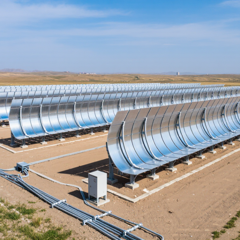
How to Choose a 1 Axis Solar Tracking System?

Understanding How a 1-Axis Solar Tracking System Works

How to Choose a 1 Axis Solar Tracking System?

Understanding How a 1-Axis Solar Tracking System Works

A 1-axis solar tracking system rotates photovoltaic panels around one main axis. Most systems follow the sun from east to west during the day. The panel angle changes gradually, rather than moving in several directions. The movement is simple.

A controller receives position data from astronomical calculations or light sensors. It then signals a motor and gearbox to adjust the mounting structure. Many designs use a horizontal north-south axis, while the rotation follows the sun’s daily path. This arrangement can improve sunlight exposure compared with fixed panels, especially in regions with strong direct sunlight.

Choosing a suitable system requires more than checking its tracking range. Examine wind conditions, soil strength, row spacing, and local maintenance access. A robust structure should resist vibration and include a safe position for severe weather. Backtracking can reduce row-to-row shading when the sun sits low. That detail matters on tightly packed sites.

Energy estimates should come from measured solar data, not optimistic brochures. Dust, cloudy periods, motor losses, and imperfect alignment reduce actual production. A tracker may generate more electricity, but it also introduces moving parts, wiring, and maintenance needs. In field planning, I would compare the expected gain against cleaning schedules, replacement access, and seasonal weather. The best design is not always the one with the widest movement.

How to Choose a 1-Axis Solar Tracking System?

Understanding How a 1-Axis Solar Tracking System Works

This representative mid-latitude planning scenario compares monthly energy yield from a fixed-tilt photovoltaic system with a north–south 1-axis tracking system. The tracker rotates modules during the day to follow the sun’s east-to-west movement, increasing energy production during morning and afternoon hours.

In this example, the fixed-tilt system produces approximately 1,332 kWh/kWp annually, while the 1-axis tracking system produces approximately 1,470 kWh/kWp—an increase of about 10%. Actual results depend on latitude, terrain, row spacing, system availability, shading, weather, and tracker configuration.

Assessing Site Conditions and Solar Movement

How to Choose a 1 Axis Solar Tracking System?

Site conditions should guide the tracker choice more than headline efficiency. A north-south axis follows the sun’s daily east-to-west movement. Seasonal solar height still changes throughout the year. Measure latitude, terrain slope, horizon shading, and row spacing before selecting equipment. A steep east-west slope can create uneven morning and afternoon exposure. Uneven exposure reduces the value of tracking.

NREL’s PVWatts documentation uses hourly solar position, array geometry, and shading inputs to estimate photovoltaic output. Use similar detail during the assessment. Record shadows at 9 a.m., noon, and 3 p.m. across several months. The map may look clear. It can still mislead. A site near tall trees, ridges, or transmission structures may need backtracking. Backtracking reduces row-to-row shade when the sun sits low. It may also reduce theoretical energy gain.

IEA PVPS Trends 2024 reports roughly 446 GW of new photovoltaic capacity worldwide in 2023, bringing global capacity above 1.4 TW. This expansion increases pressure to match system design with local conditions. Compare the tracker’s operating range with the site’s slope and wind exposure. NREL’s 2024 Annual Technology Baseline treats single-axis tracking as a common utility-scale configuration, especially where direct sunlight is strong. Still, diffuse or cloudy climates can weaken the advantage. Soil bearing tests, drainage checks, and wind studies matter. A spreadsheet cannot replace field evidence.

Comparing Tracker Designs, Drive Systems, and Control Methods

How to Choose a 1 Axis Solar Tracking System?

A 1-axis tracker can increase energy yield, but design choice matters more than headline gains. IEA PVPS Task 13 reports that tracking performance depends strongly on terrain, weather, and operating quality. In many utility-scale projects, single-axis tracking can deliver roughly 15–25% more annual energy than fixed-tilt systems. That range is not guaranteed. My first design check would be the site’s wind, slope, soil, and row spacing.

Tracker designs usually follow north-south axes, with modules rotating east to west. Horizontal systems suit flatter land and reduce shading between rows. Tilted-axis designs may improve winter production, but foundations and construction become more complicated. The drive system also deserves attention. A centralized motor can reduce equipment count, while distributed drives may limit losses after one actuator fails. Gear backlash, corrosion, and emergency stow behavior need field testing. Small weaknesses become expensive at scale.

Control methods range from astronomical algorithms to sensor-assisted tracking. Astronomical control is predictable and easier to audit. Sensors can respond to unusual sunlight, but dust or partial shading may create poor commands. NREL’s System Advisor Model and the IEA PVPS reliability guidance both support site-specific simulations before procurement. Compare annual yield, parasitic power, availability, maintenance hours, and replacement access. Not only peak output. A cheaper tracker may win on paper, yet lose during repeated high-wind stow events. That is an uncomfortable result. Keep uncertainty visible, and require measured operating data during acceptance testing.

How to Choose a 1 Axis Solar Tracking System? — Comparing Tracker Designs, Drive Systems, and Control Methods
Comparison Dimension Option Typical Technical Characteristics Advantages Limitations and Risks Best-Fit Application Overall Suitability
Tracker Geometry Horizontal single-axis tracker Rotates from east to west around a horizontal north–south axis. Common operating range is approximately ±45° to ±60°, depending on layout and latitude. Good balance between energy gain, mechanical complexity, and land use. Usually well suited to utility-scale photovoltaic fields. Requires row-to-row shading analysis and adequate site width. Energy gain decreases at high latitudes or where the solar resource is diffuse. Large ground-mounted projects in low- to mid-latitude regions with relatively open terrain. ★★★★★
Tracker Geometry Tilted single-axis tracker Rotates around an axis inclined toward the local latitude or a site-specific angle. Can improve geometric alignment with the sun in some locations and may reduce the required rotational range. Inclined foundations and supports can increase structural and installation complexity. Terrain adaptation may be less straightforward. Sites where latitude, terrain, or annual solar geometry justifies an inclined axis. ★★★★☆
Tracker Geometry Vertical single-axis tracker Rotates around a vertical axis, allowing the module plane to face different azimuth directions. Can be useful for high-latitude or steeply sloped sites and may offer favorable winter orientation in selected locations. Often needs larger spacing to control shading. It may provide less annual benefit than horizontal tracking in many conventional solar farms. High-latitude locations, sloped sites, or projects with unusual solar-orientation requirements. ★★★☆☆
Tracker Geometry Rotational axis aligned with terrain Rows follow local topography rather than a perfectly uniform plane. The axis may be slightly adjusted to reduce grading. Can reduce earthwork and improve constructability on rolling terrain. Uneven row geometry can complicate backtracking, calibration, drainage, and electrical layout. Undulating sites where minimizing grading is more valuable than achieving a uniform array plane. ★★★★☆
Module Configuration One module row per torque tube Each tracker row carries a relatively narrow module string arrangement on one drive structure. Lower row-level mechanical loading and simpler independent movement. More drives, controllers, foundations, and potential maintenance points per megawatt. Sites requiring flexible row control or where terrain changes frequently across the field. ★★★★☆
Module Configuration Multiple module rows linked mechanically Several rows or long torque tubes are synchronized through linkages, shafts, or coordinated controls. Fewer drive units can reduce equipment count and simplify centralized operation. Longer structures experience greater torsional and wind loads. Misalignment or a mechanical fault can affect more modules. Large, relatively flat sites with consistent geotechnical and wind conditions. ★★★★☆
Drive System Electromechanical linear actuator Uses a motor-driven screw, gearbox, or similar mechanism to create linear motion that rotates the tracker row. Compact, controllable, and suitable for distributed row-level operation. Can provide high positioning accuracy. Moving seals, gears, and screws require protection from dust, moisture, corrosion, and inadequate lubrication. Projects needing independent row control, moderate row length, or precise positioning. ★★★★☆
Drive System Rotary slew drive Uses a geared rotary mechanism, commonly with a worm or planetary gear arrangement, mounted near the rotation point. High torque density, compact installation, and resistance to back-driving when properly specified. Gear wear, backlash, lubrication, and thermal performance must be checked over the expected operating life. Medium- to large-scale trackers requiring strong torque transmission and controlled angular movement. ★★★★★
Drive System Centralized mechanical drive A motor and gearbox transmit motion through a shaft, linkage, or multiple mechanical sections. Can reduce the number of motors and electrical devices, potentially simplifying field wiring. Mechanical tolerances accumulate over long distances. A single drive failure may influence a large tracker section. Uniform, accessible sites where centralized maintenance and mechanical simplicity are priorities. ★★★★☆
Drive System Distributed drive architecture Multiple independently powered drives operate separate rows or short tracker sections. Limits the impact of a single failure and can adapt better to irregular terrain and row-specific conditions. More motors, controllers, communications devices, and maintenance points increase system complexity. Uneven terrain, segmented arrays, and projects prioritizing fault containment. ★★★★☆
Control Method Astronomical algorithm Calculates the sun’s position using time, date, geographic coordinates, and the tracker’s axis geometry. Does not require a light sensor and provides repeatable positioning under clear or cloudy conditions. Accuracy depends on correct time synchronization, geographic settings, axis calibration, and mechanical installation. Most utility-scale projects, especially where predictable and low-maintenance control is required. ★★★★★
Control Method Light-sensor feedback Uses one or more photodiodes or irradiance sensors to adjust the array toward the strongest light signal. Can compensate for some installation errors and local optical conditions. Clouds, reflections, sensor soiling, shading, and diffuse irradiance can cause unstable or inaccurate movement. Specialized systems, experimental installations, or applications requiring local optical feedback. ★★★☆☆
Control Method Hybrid astronomical and sensor control Uses calculated solar position as the primary reference and sensors for calibration, verification, or fault detection. Combines predictable operation with the ability to detect tracking errors and certain mechanical or sensor faults. Higher control-system complexity and additional commissioning requirements. Projects seeking enhanced monitoring, calibration, and operational diagnostics. ★★★★★
Wind Protection Fixed-angle wind stow Moves rows to a predetermined low-load angle when wind speed exceeds a configured threshold. Simple, fast, and relatively easy to validate through structural analysis. A fixed angle may not be optimal for every wind direction or local terrain condition. Most standard utility-scale sites with well-characterized wind conditions. ★★★★★
Wind Protection Adaptive wind stow Adjusts the stow angle using wind speed, direction, structural limits, and sometimes row-level measurements. May reduce wind loading more effectively in complex or variable conditions. Requires more sensors, validated algorithms, reliable communications, and careful fail-safe design. High-wind, complex-terrain, or highly engineered projects with advanced monitoring infrastructure. ★★★★☆
Backtracking Time-based backtracking Changes the tracking angle during morning and evening periods to reduce row-to-row shading based on sun position. Simple, predictable, and effective for regular row spacing and uniform terrain. Performance can decline where terrain height varies significantly between rows. Flat or gently sloped sites with consistent row geometry. ★★★★★
Backtracking Terrain-aware backtracking Uses row elevation, slope, azimuth, and array geometry to calculate different angles for different tracker sections. Can reduce shading on uneven sites while preserving more available irradiance. Requires accurate topographic data, detailed commissioning, and more advanced control software. Hilly or irregular sites where uniform backtracking would create avoidable shading. ★★★★★
Site and Climate High-wind coastal or open plain site Requires careful structural loading analysis, robust stow logic, corrosion protection, and reliable emergency positioning. Single-axis tracking can deliver strong energy production when wind and stow requirements are properly engineered. Structural reinforcement, foundations, and operating restrictions may increase capital and maintenance costs. Projects with bankable wind data and a clear structural design basis. ★★★★☆
Site and Climate Dusty or high-soiling environment Requires sealed drive components, corrosion-resistant materials, accessible inspection points, and a cleaning strategy. Tracking can improve energy yield without increasing module count, provided mechanical parts remain reliable. Dust can affect sensors, bearings, gears, and electrical connectors. Cleaning and preventive maintenance are important. Arid sites with established soiling measurements and planned maintenance access. ★★★★☆
Maintenance and Reliability Row-level monitoring and fault isolation Measures motor current, position, drive status, communications, and stow condition for individual rows or sections. Shortens troubleshooting time and limits energy losses when a fault occurs. Requires reliable communications, data management, spare parts, and trained maintenance personnel. Large projects where availability, diagnostics, and operational transparency are priorities. ★★★★★
Selection Priority Lowest initial equipment cost Favors fewer sensors, simpler controls, shorter structures, and limited mechanical redundancy. May reduce upfront procurement and installation expenditure. Can increase long-term operating risk, downtime, or maintenance cost if reliability and serviceability are underdeveloped. Projects with strong in-house maintenance capability and moderate environmental conditions. ★★★☆☆
Selection Priority Lowest levelized cost of energy Balances energy gain, capital cost, site preparation, availability, maintenance, replacement parts, and operating life. Provides a more complete economic basis than comparing tracker purchase price alone. Requires accurate site data, energy modeling, wind assessment, reliability assumptions, and lifecycle cost analysis. Bankable utility-scale projects and long-term asset ownership. ★★★★★
Practical selection note: Confirm the tracker’s structural loads, stow behavior, corrosion protection, operating temperature range, control accuracy, communications architecture, spare-parts plan, and expected availability using project-specific wind, terrain, irradiance, soil, and maintenance data. Energy gains and cost outcomes vary by site; they should be validated with a location-specific production and lifecycle-cost model.

Evaluating Energy Gains, Costs, Maintenance, and Durability

A one-axis solar tracking system should be judged by energy gained, not movement alone. NREL modeling commonly shows 15–25% higher annual energy yield than fixed-tilt systems. The gain is strongest in clear, high-irradiance regions. It may shrink under frequent clouds, strong winds, or heavy morning shading. Site data matters more than brochure estimates.

Cost analysis must include motors, controllers, foundations, wiring, commissioning, and replacement parts. The IEA PVPS Task 13 reliability reports identify moving components as additional inspection points in photovoltaic plants. Tracking can also increase operational complexity and maintenance visits. A failed actuator can leave an entire row in an inefficient position. That detail is easy to overlook. Compare lifetime energy, not only the initial price.

Durability depends on wind design, corrosion protection, drainage, and service access. NREL’s Annual Technology Baseline indicates that tracking is widely considered in utility-scale PV because its energy advantage can support competitive lifecycle economics. However, local wind loads and soil conditions can change the result. Ask for measured availability data, spare-part lead times, and warranty exclusions. A practical trial row may reveal problems that a spreadsheet misses. Sometimes, simpler wins.

Selecting the Right System for Your Solar Project

How to Choose a 1 Axis Solar Tracking System?

Selecting the Right System for Your Solar Project

Selecting a one-axis solar tracker starts with the site, not the sales brochure. Measure slope, soil conditions, row spacing, wind, snow, and access routes. These details determine whether energy gains justify civil works and maintenance costs. Flat land helps. Uneven ground may require specialized foundations or wider clearance between rows.

Use local irradiance data to estimate realistic production gains. A reliable assessment should compare fixed-tilt output, tracker performance, installation costs, and long-term operating expenses. Do not rely on ideal laboratory figures alone. Field measurements matter. Check whether the system supports your module dimensions, electrical layout, and planned ground coverage ratio. Review wind stow behavior, emergency controls, corrosion protection, and sensor redundancy.

Maintenance access deserves equal attention. Technicians need safe routes, practical replacement procedures, and clear monitoring data. Ask for documented testing, structural calculations, warranty terms, and performance records from comparable climates. A low purchase price can become expensive when motors, bearings, or controllers are difficult to service. That is easy to overlook. Designers should also test drainage and foundation assumptions before construction. Small errors here may delay an entire project. No model is perfect, especially when weather patterns change. A cautious design leaves room for uncertainty rather than promising maximum output every day.

FAQS

What does a one-axis solar tracking system do?

It rotates photovoltaic panels around one main axis. Most systems follow the sun from east to west. The movement is gradual and simple.

How does the tracker know when to move?

A controller uses solar position calculations or light sensors. It signals a motor and gearbox to adjust the panel structure. Sensor readings can be imperfect.

Can one-axis tracking produce more electricity than fixed panels?

It can improve sunlight exposure in regions with strong direct sunlight. The actual gain depends on weather, dust, shading, and alignment. The advantage can shrink.

Which site conditions should be checked before installation?

Measure latitude, terrain slope, soil strength, wind, snow, drainage, and horizon shading. Inspect shadows at 9 a.m., noon, and 3 p.m. Field evidence matters.

Why is row spacing important?

Closely spaced rows can shade one another when the sun is low. Backtracking changes the panel angle to reduce this shading. It may reduce theoretical energy gain.

Is a one-axis tracker suitable for cloudy regions?

Its benefit may weaken when diffuse light dominates. Compare local irradiance data with fixed-tilt production estimates. Do not trust ideal figures alone.

What maintenance issues should project owners expect?

Moving parts create extra needs for inspections, cleaning, wiring checks, and replacement access. Technicians need safe routes and clear monitoring data. A cheap purchase can become expensive.

How should a suitable tracking system be selected?

Compare energy gains, foundations, installation costs, maintenance, and long-term operating expenses. Check module dimensions, wind stow behavior, corrosion protection, and emergency controls. I would not promise maximum output.

Conclusion

Choosing a 1 Axis Tracking Solar Panel system requires a clear understanding of how single-axis tracking follows the sun’s daily movement to improve energy production. Start by assessing the project location, including latitude, terrain, shading, wind exposure, soil conditions, and available space. These factors determine whether a horizontal or tilted tracking arrangement is suitable and how effectively it can capture sunlight throughout the year.

Next, compare tracker structures, drive mechanisms, and control methods, considering reliability, operating precision, installation requirements, and compatibility with the solar array. Energy gains should be evaluated against equipment, installation, land preparation, and operating costs. Maintenance needs, weather resistance, component durability, and long-term service access are equally important. The best system is not always the one with the highest theoretical output, but the option that provides a balanced combination of energy performance, affordability, stability, and dependable operation for the specific solar project.


Mason

Mason

Mason is a seasoned marketing professional with a deep expertise in the company's offerings and a passion for driving brand awareness. With a strong background in digital marketing strategies, he has an innate ability to connect with diverse audiences and effectively communicate product benefits.......